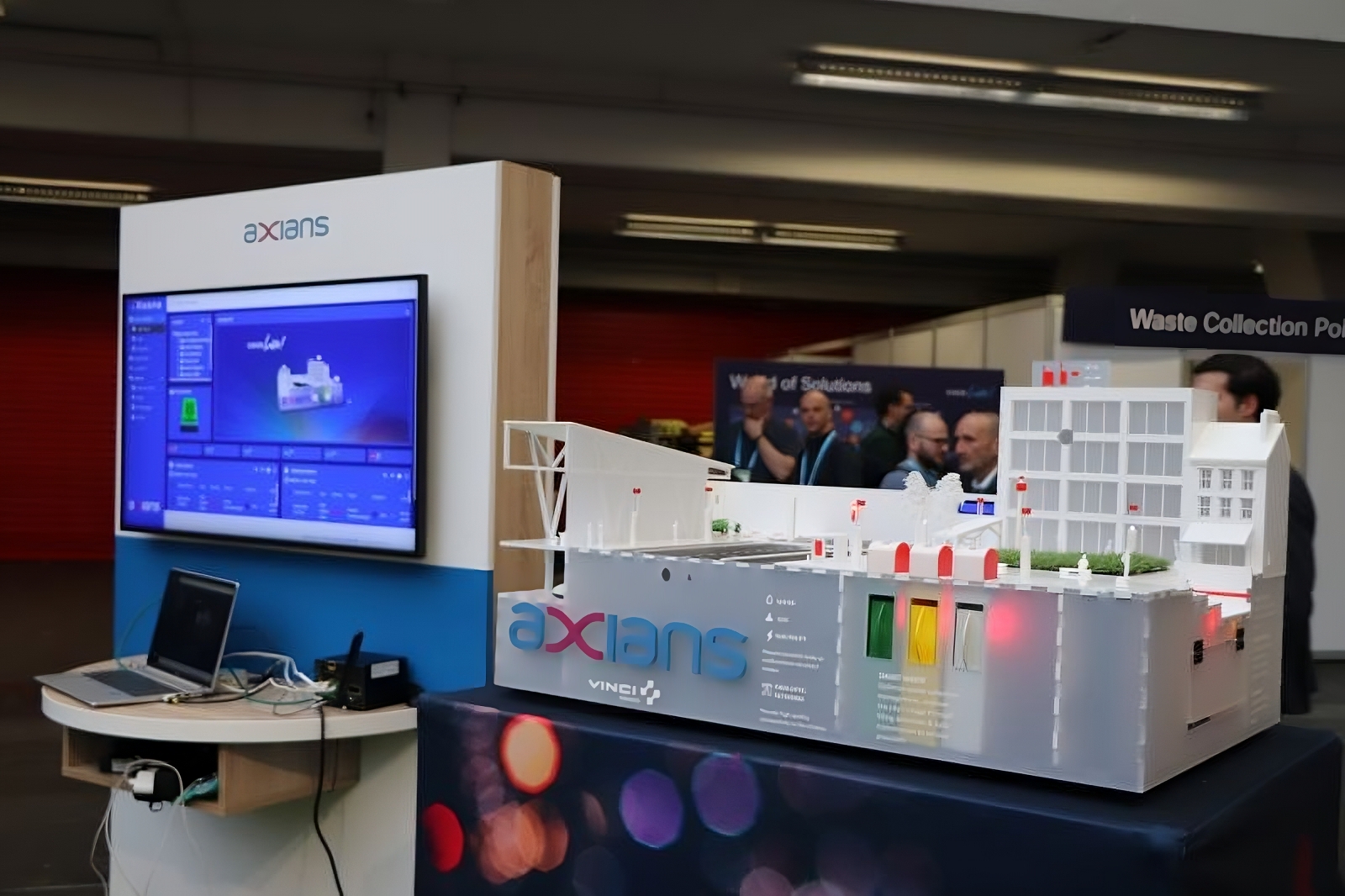
A smart city model that I helped build a few years back, to better explain what IoT could mean for a city:
what & why
When I arrived at $old_job in 2019, one of my first project was to build a small scale, smart city model that could :
- be tranported anywhere,
- be installed on a table easily
- show what improvements to city life could be made using IoT
- and be pretty to lure people on our stands ;)
The actual model was built by architecture students, with whom I devised a plan to integrate various sensors, LEDs and interactive elements to play with. The whole thing took around a week to be finished.
The model has been on display at Cisco Live 2019 and 2024 (that’s the picture above), at various events in France (Salon des Maires..) and is now at Axians in La Defense.
how
Full code is here: https://github.com/k0rventen/smartcity
Here is a quick diagram showing every major component of the model :
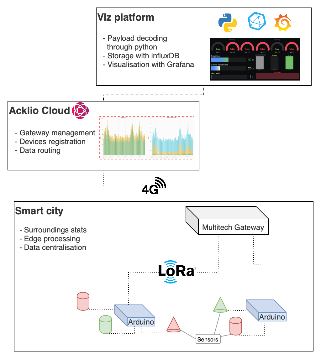
- Various sensors (temperature, humidity, noise, parking spots..) are connected to Arduinos equipped with LoRa antennas, that transmits to a nearby 4G LoRa gateway.
- Data & management informations are uploaded to our Acklio server.
- Actual sensor data is retrieved by an AWS instance for decoding/storage/visualisation.
Each section below is describing one of those components.
Hardware listing
Here is a list of the hardware components used in the smart city model :
- 3 Arduino Uno as micro-controllers, on top of which sits:
- Grove Hat for easy cable management, with the following sensors :
- A LoRaWAN antenna, to upload the gathered data to a nearby gateway,
- A Multitech LoRa gateaway, to receive the payloads from the antenna
Each arduino is responsible for a specific task :
- Arduino 1 is managing the street lamps and monitoring the temperature / noise level of the city,
- Arduino 2 is managing the city’s trash cans
- Arduino 3 is managing the parking spots
Configuration adjustements
The same boilerplate file is deployed to every arduino. The logic is the same everywhere, the arduino fetches the sensors and uploads their data to the cloud through an LoRa gateway. The only difference between each Arduino is which sensors are connected and on which pin.
This is the configuration currently is use in the model in header.hpp.
int UltrasonicSensors[] = {2,3,4};
int HallSensors[] = {6,7,8,2,3,5};
int TemperatureSensor = A2;
int SoundSensor = A3;
int BrightnessSensor = A1;
int FloodSensor = 2;
int FloodLED = 3;
int WasteLEDs[] = {6,7,8};
int ParkingLEDS[] = {A2,A3,9,4,A0,A1};
int StreetLampsNumber = 8;
ChainableLED StreetLamps(4,5, StreetLampsNumber);

const int RUNTIME_INTERVAL = 1000;   //! time in ms between runs
This header.hpp reflects:
- which scenarios are being used by this arduino (using the
#DEFINEstatements) - which sensors are connected to the arduino and their positions on the Grove Hat.
Scenarios
The scenarios are also defined in the .hpp file, so they are only compiled/present on the arduinos that need them.
For example the parking scenario, which returns the occupancy for 6 parking spots on the model:
#ifdef PARKINGSCENARIO
/**
 * @brief Scenario that controls the parking spots of the city.
 *
 * Each parking spot is monitored and connected to a LED.
 * If the parking sport is taken, the LED is up.
 *
 */
void ParkingScenario()
{

    for (int i = 0; i < HallSensorsLen; i++)
    {
        bool isTaken = !digitalRead(HallSensors[i]);
#ifdef DEBUG
        Serial.print("\t");
        Serial.print(i);
        Serial.print(" -> ");
        Serial.println(isTaken);
#endif
        if (isTaken)
        {
            SetLedStatus(ParkingLEDS[i], HIGH);
            LoRaPayload[i * 2] = '1';
        }
        else
        {
            SetLedStatus(ParkingLEDS[i], LOW);
            LoRaPayload[i * 2] = '0';
        }
    }
}
#endif
Payload structure of the LoRa frame
Each arduino has it’s own various data to send, so each payload is different :
Garbage scenario
| Byte num | 0 | 1 | 2 | 3 | 4 |
|---|---|---|---|---|---|
| Desc | Trash 1 | Null | Trash 2 | Null | Trash 3 |
| Value | 1 | 0 | 1 | 0 | 1 |
Explanations :
- Trash : 1 means the trashcan is full, 0 means it’s not.
Parking scenario
| Byte num | 0 | 1 | 2 | 3 | 4 | 5 | 6 | 7 | 8 | 9 | 10 |
|---|---|---|---|---|---|---|---|---|---|---|---|
| Desc | Parking 1 | Null | Parking 2 | Null | Parking 3 | Null | Parking 4 | Null | Parking 5 | Null | Parking 6 |
| Value | 1 | 0 | 1 | 0 | 0 | 0 | 1 | 0 | 0 | 0 | 1 |
Explanations :
- Parking : 1 means the parking spot is taken, 0 means it’s free.
Street lamps & metrics scenario
| Byte num | 0 | 1 | 2 | 3 | 4 | 5 | 6 | 7 | 8 | 9 | 10 | 11 | 12 | 13 | 14 | 15 |
|---|---|---|---|---|---|---|---|---|---|---|---|---|---|---|---|---|
| Desc | Lights status | Null | Null | Flood status | Null | Null | Null | Null | Null | Null | Light level | Light level | Noise | Noise | Temp | Temp |
| Value | 1 | 0 | 0 | 1 | 0 | 0 | 0 | 0 | 0 | 0 | 8 | 9 | 4 | 8 | 2 | 5 |
Explanations :
- Lights status : 1 means the lights are on, 0 means off.
- Flood status : 1 means flood detected, 0 means no flood detected
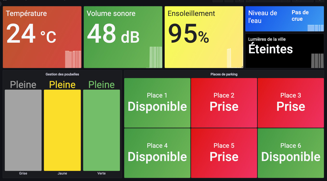
- Light level : Bytes 10 and 11 are forming a numnber reflecting the percentage of light perceived by the sensor, here 89%.
- Noise : Bytes 12 and 13 are the current noise level reading in decibels. Here is 48 dB.
- Temp : Bytes 14 and 15, the current temperature reading in Celsius, here 25°C.
cloud platform
A ‘cloud’ platform gathers the data sent by the model through a LoRa GW. It’s a simple python worker that translates MQTT messages to influxDB. The latter is used by Grafana to display ’live’ and historical data: